
Resources
TAG-X Smart Rail installation guide
How a TAG-X Smart Rail goes on the wall, step by step. Read the full instructions before you start, and have a certified electrician do all wiring.
Before you start
Warning
- Turn off power to the electrical circuit before installing or modifying wiring.
- All wiring must meet local, state and federal codes and be done by a certified electrician.
- Do not connect power until the Smart Rail installation is complete.
Tips
- Cut covers up to 1/16 in (1.6 mm) longer for a tight fit.
- Read the full installation instructions before you begin.
Tools
Safety glasses; tape measure; 3/8 in socket (machine-screw hex bolt) and 7/16 in socket (wood-screw hex bolt); level; power drill; 1/4 in masonry drill bit for concrete or concrete block; power miter saw with a 10 in blade, 60–80 carbide-tipped teeth; shears; utility knife.
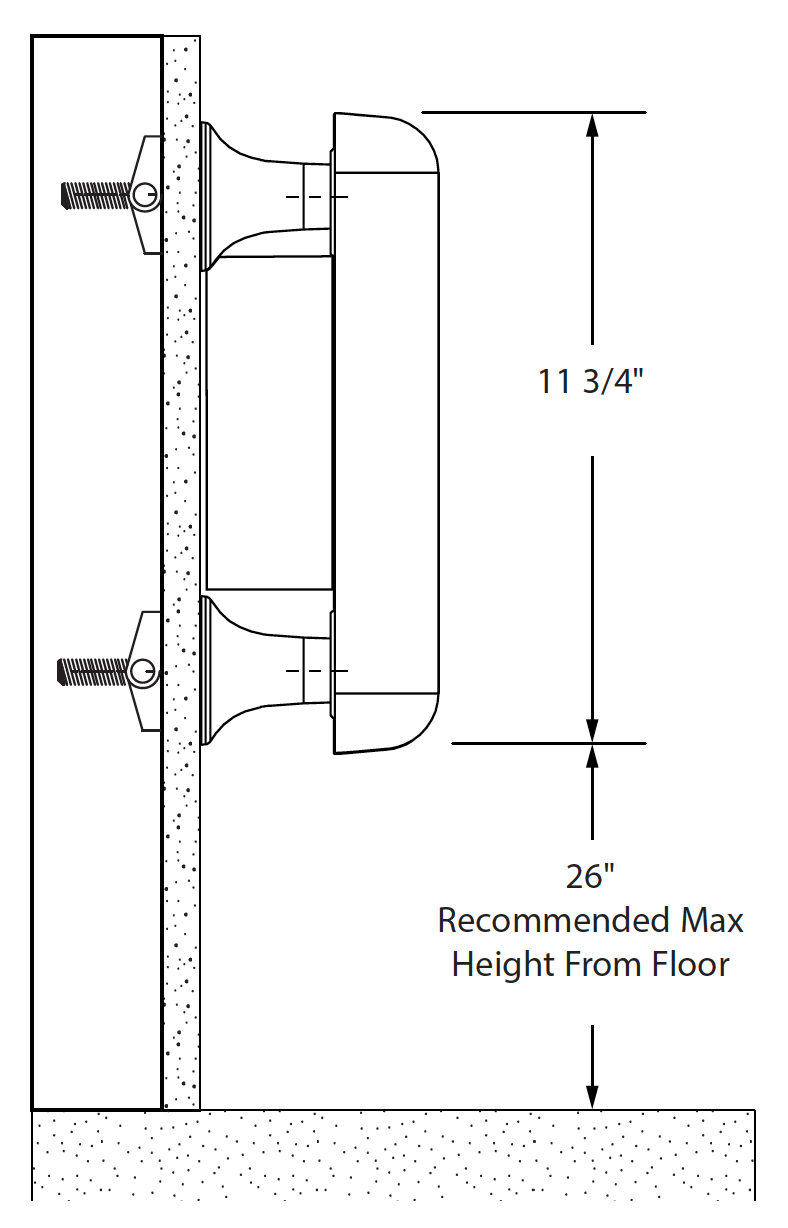
Layout
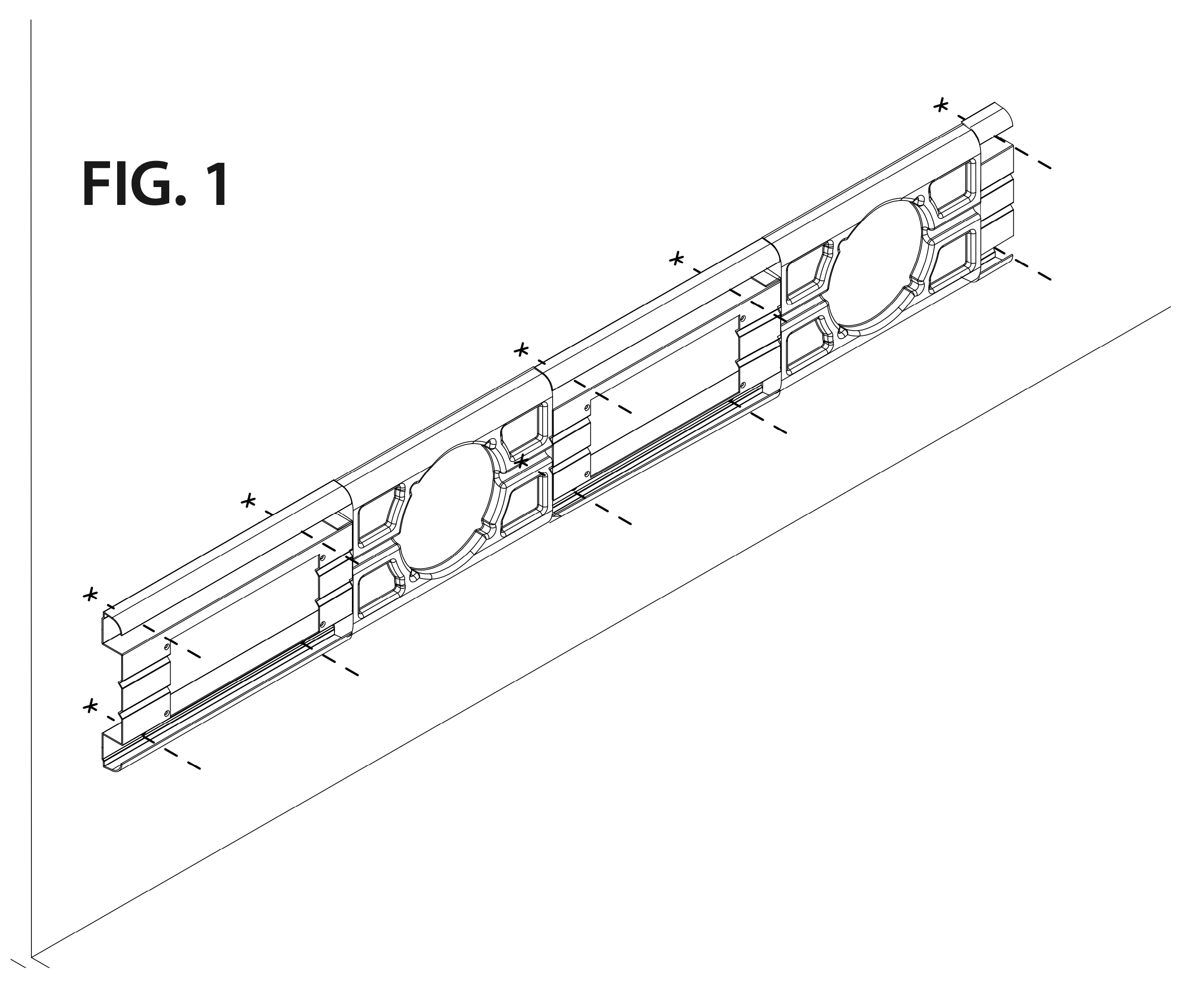
Components and layout

Step 1
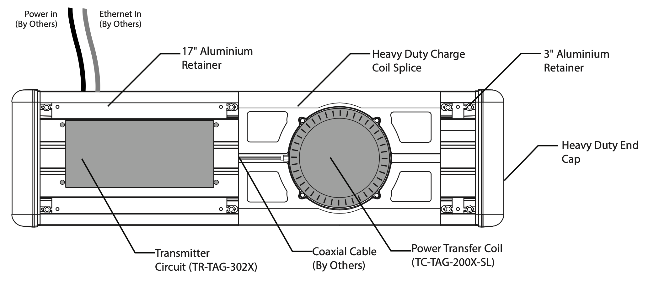
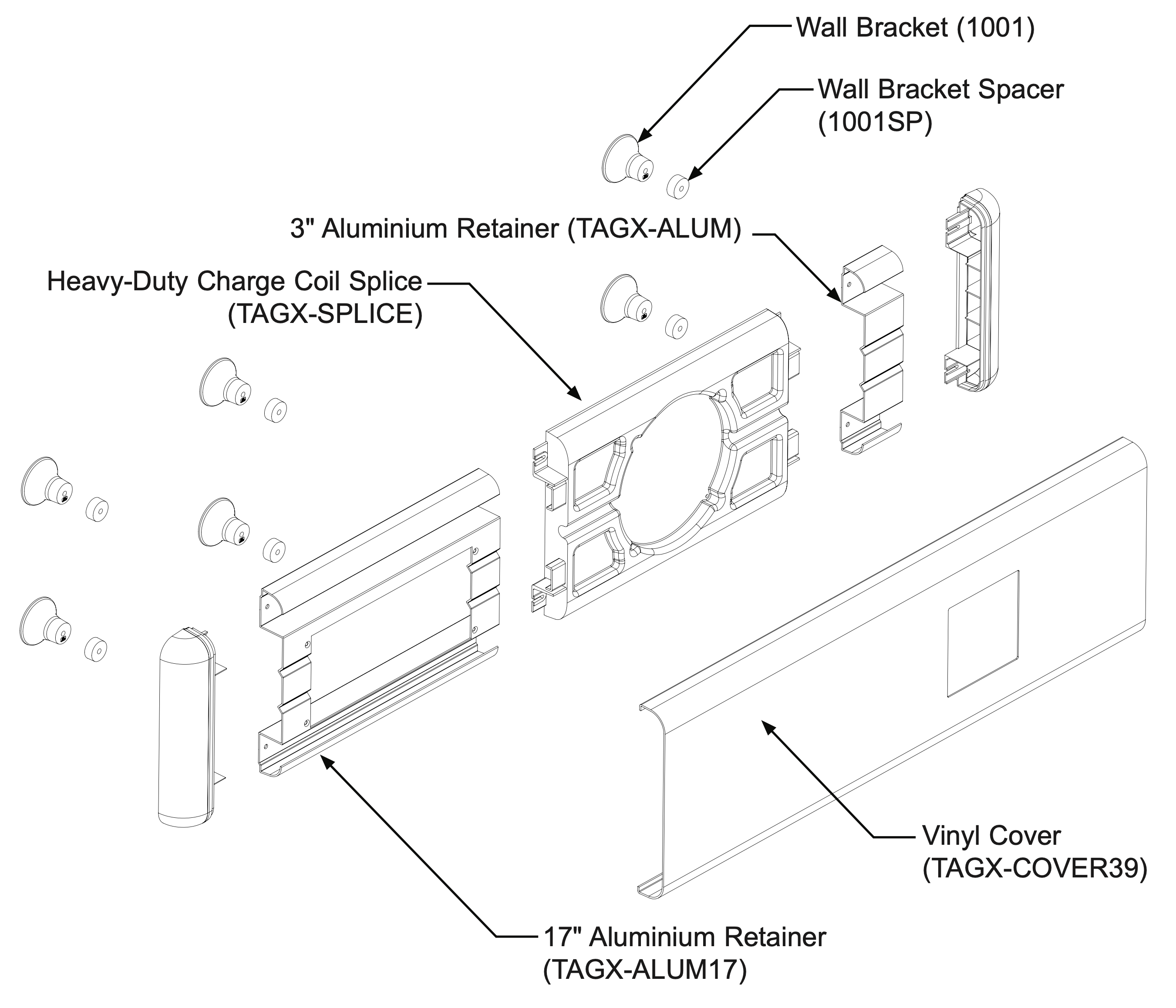
- Pre-assemble the 17 in aluminum retainers, heavy-duty charge coils and 3 in aluminum retainers with the supplied 1/4-20 × 1 in hex-head flange bolts and nuts (heads on the back, threads pointing out within the wings of the retainer).
- Hold the assembly against the wall at the right height (no more than 26 in above the finished floor, per ADA).
- Mark the bracket holes on the wall through the pre-drilled holes in the retainer.
- Remove the assembly and pre-drill the holes with a 3/4 in bit.
Step 2
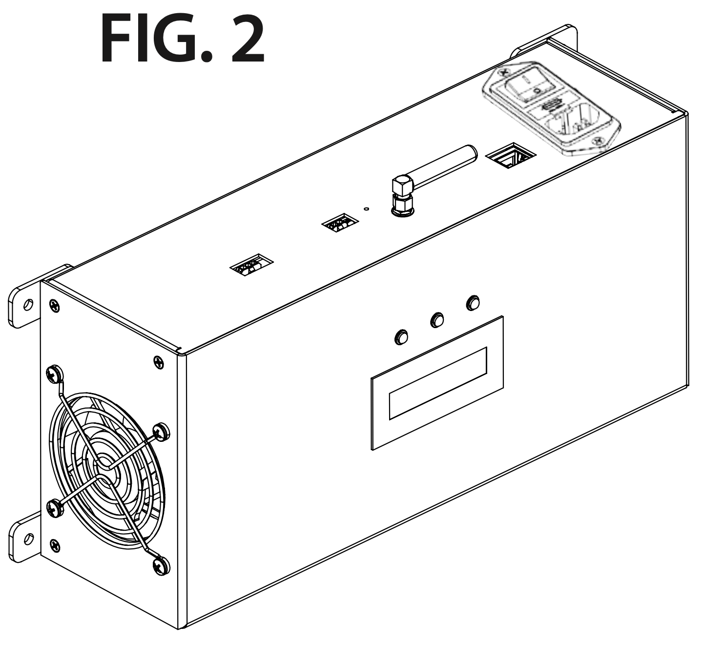
- Before installation, unscrew the power switch from the transmitter circuit, lift it gently from the housing and turn it 180° so it matches the drawing (plug side towards the LEDs).
- Mount the transmitter circuit to the 17 in retainer with the supplied flat-head screw and nut.
Step 3
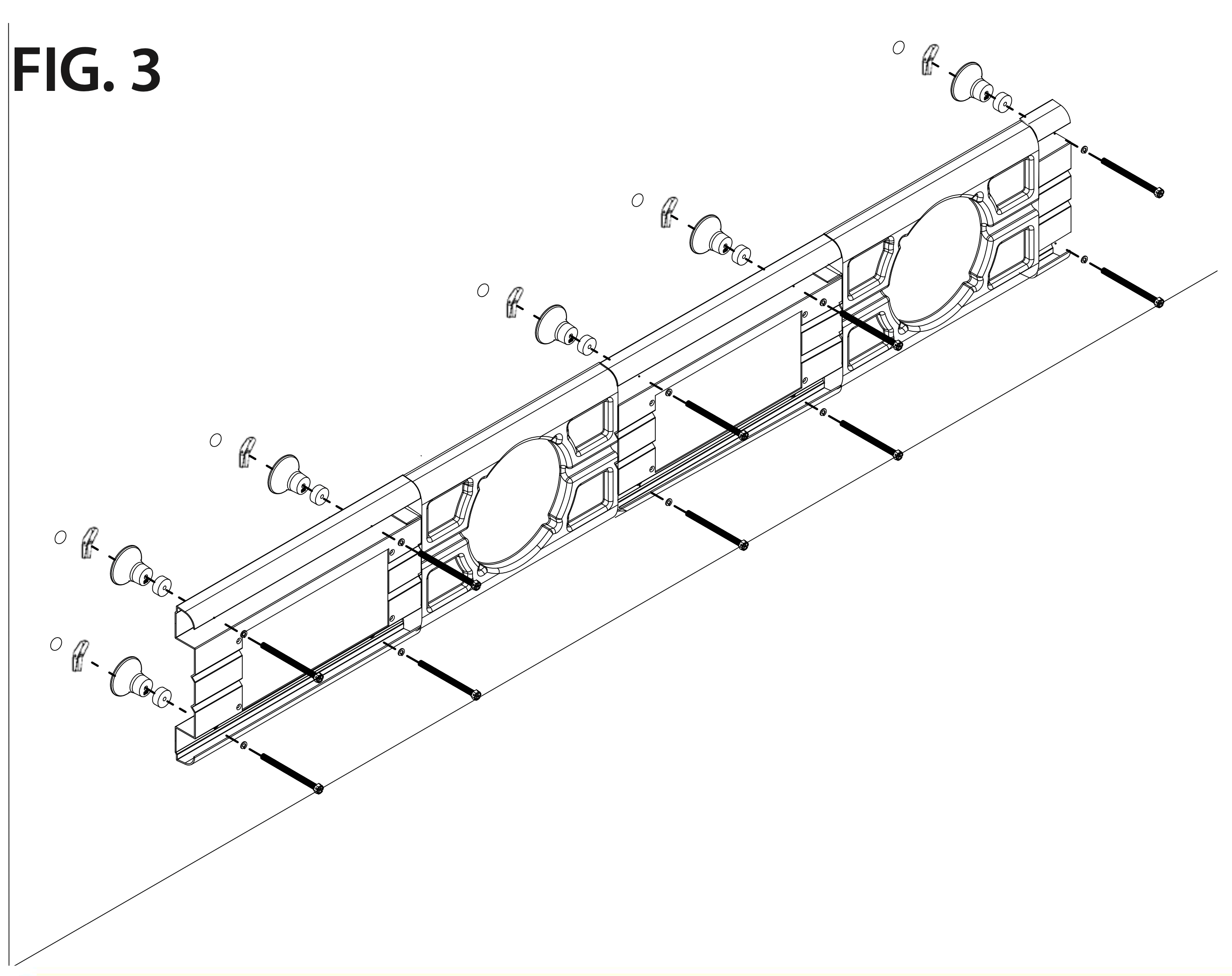
- Pre-thread the mounting hardware. Make sure the toggle anchors are loose enough to go fully into the pre-drilled holes.
- With the anchors in the holes, tighten the fasteners to secure the rail to the wall.
- Connect the power and Ethernet cables (by others) to the transmitter circuit. Do not turn the unit on until installation is complete.
Step 4
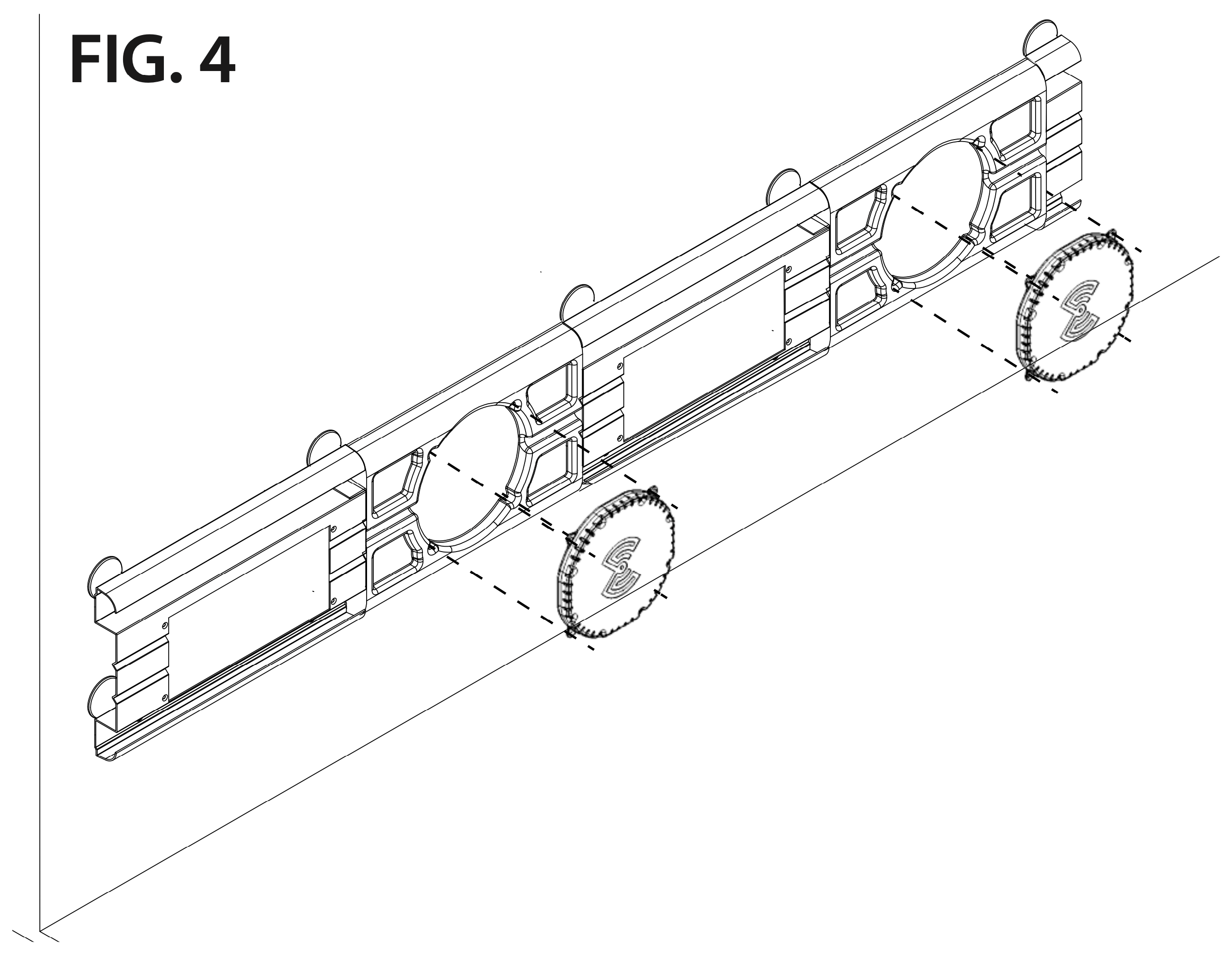
- Before installing the power transfer coil, attach the coaxial cable to the transmitter circuit.
Step 5
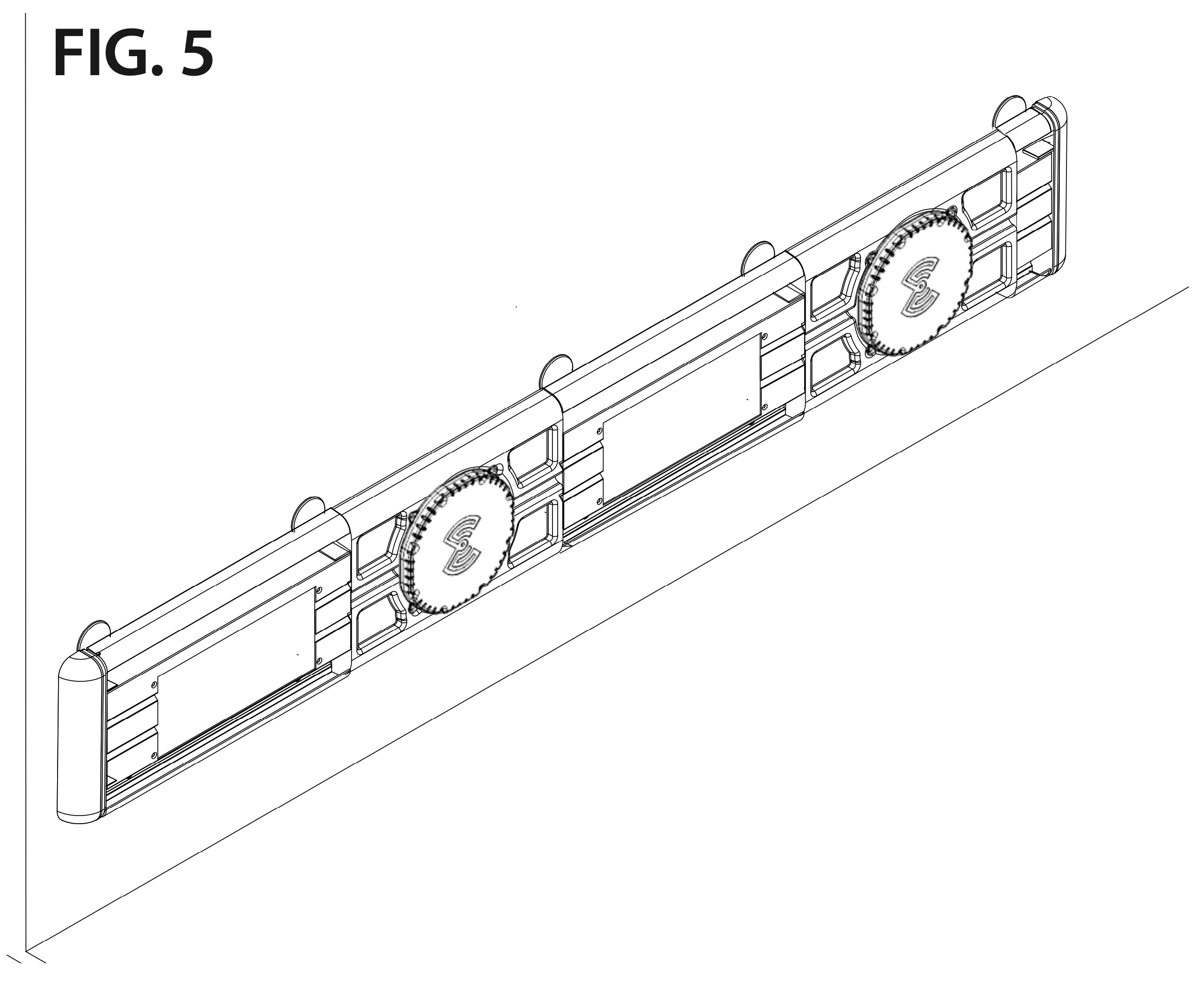
- Run the coaxial cable through the recessed groove in the heavy-duty charge coil splice, and attach the charge coil to the power transfer coil.
- Place the power transfer coil in the recessed pocket of the splice and fasten it with the supplied plastic screws and nuts.
- Attach the end caps to both ends of the rail with the supplied 1/4-20 × 1 in flanged-head screws and nuts.
Step 6
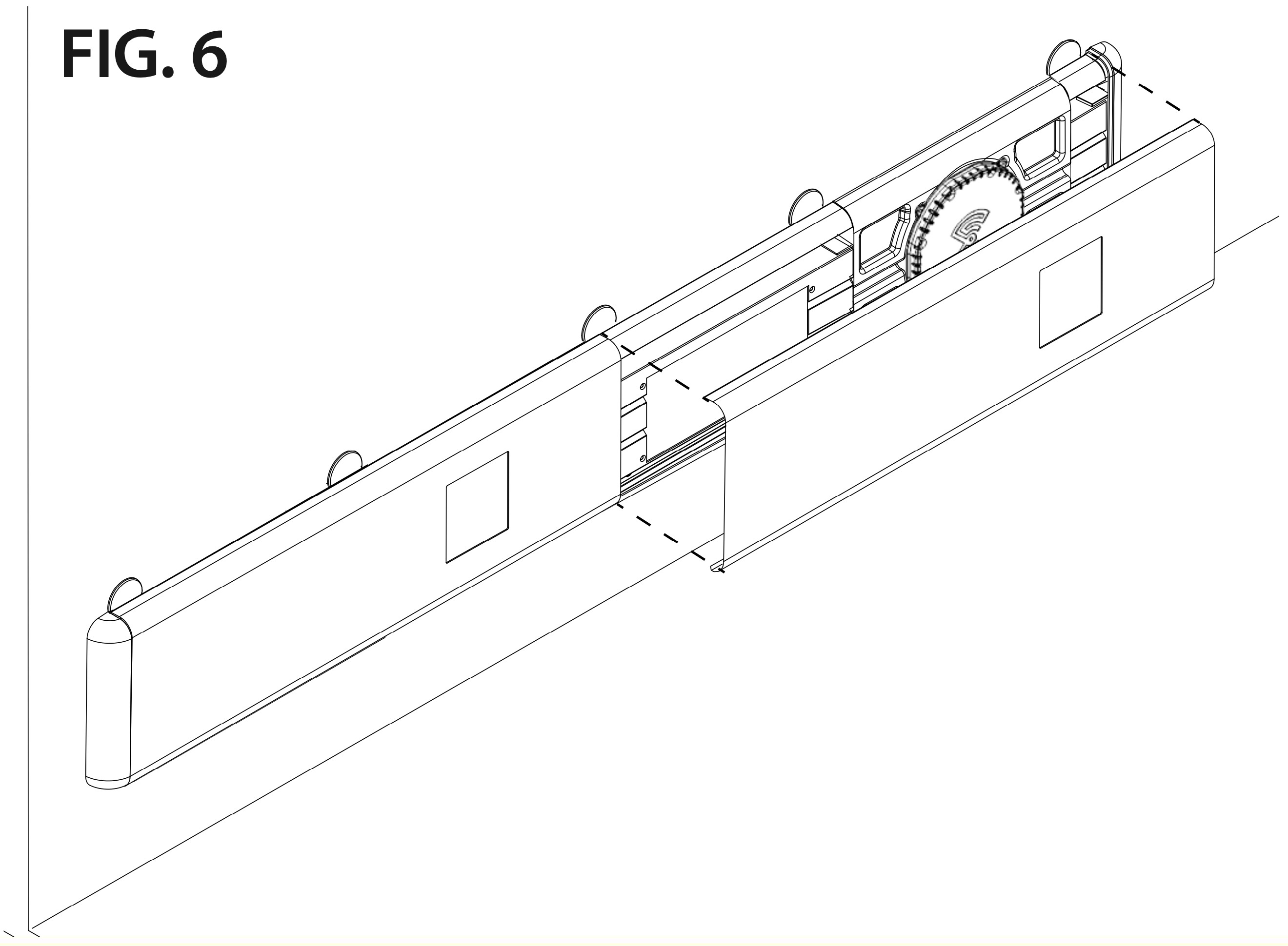
- Covers come in set lengths and need trimming to suit production tolerances. When dry-fitting, center the machined pocket in the cover over the power transmitter coil.
- Cut vinyl with a fine-toothed finish blade for a clean, smooth cut.
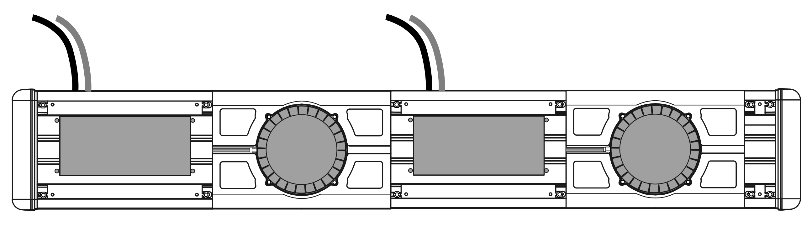
- Snap the covers onto the rail; repeat for the next section of rail, if any.
- Clean the cover’s recessed pocket with rubbing alcohol and a lint-free cloth, then press the TAG-X label into it with firm, even pressure.
- Turn the unit on, and clean the work area.
Questions about an installation?
Call us or send the details of your walls and electrical plan, and we will help.